Sunday, March 16, 2014
Tuesday, July 2, 2013
DC motor control using PIC
When using PIC to control DC
motor, the motion of motor such as forward, reverse,and speed of
rotation can be programmed. If the motion of motor only required forward
and reverse without considering the speed of rotation, motor can be
control through relay module. the are two example of relay module which
can be use by PIC to control DC motor. First figure is to control only
On and OFF of motor which also compatible to other devices that are
using switch. Second figure can be used to control forward and reverse
motion of DC motor.


By
using relay module, it is very easy to control the motion of motor. The
programming part only require ON and OFF of output PORT.
Example of simple forward reverse motor control using 2 switches connected to RD0 and RD1:
main()
{
while (1)
{
TRISD = 0b00000011;
PORTB = 0b00000000;
TRISB = 0b00000000;
PORTB = 0b00000000;
if (PORTDbits.RD0 == 1 && PORTDbits.RD1 == 0)
PORTB = 0b00000010;
if (PORTDbits.RD0 == 0 && PORTDbits.RD1 == 1)
PORTB = 0b00000010;
else
PORTB = 0b00000000;
}
}
When
DC motor require speed control, the speed of DC motor can be control by
various techniques including Pulse Width Modulation (PWM), power
transistor, driver IC etc. The diagram below is example of DC motor
controlled by transistor and PWM.

Whenever
there is input voltage supplied to Base pin of the transistor, the
transistor will turned ON and let the current flow through. with
different speed of PWM provided, the speed of motor can be adjusted. The
faster the PWM signal, the faster the motor will rotate.
Friday, June 28, 2013
Analog - Digital convertion with PIC
PIC 18F4550 come with ADC in PORT A which reads analog input such as:
1. voltage
2. temperature
3. light intensity
4. resistance
5. moisture
6. humidity etc
Analog signal is converted into digital form by referring to reference voltage which can be set to Vdd (same as source voltage) or any other external reference voltage source. ADC
Module has high-voltage reference (Vref+) and low-voltage reference (Vref-). The
reference voltage value can be chose to be Vdd, VSS, RA2 or RA3. ADC Module from
Channel 0-7 (AN0-AN7) will read the voltage value detected from the chosen
channel.
Table below shows how to configure PORT A to either digital or analog I/O.


For example: configure only AN0 of PORT A as analog I/O while others are digital. An analog signal is send to AN0. The code should look like below:
ADCON0 = 0B00000001 //choose channel AN0
ADCON1 = 0B00001110 // only AN0 is analog

**ADON = turn ON ADC
**GO/DONE = conversion status
For PIC18, it is difference compare to PIC16 where PIC18 need to configure ADCON2.

ADCON2 = 0B10001010 is use for 22pF ceramic capacitor pair and 20MHz-40Mhz crystal.
1. Configure the A/D module:
• Configure analog pins, voltage reference and digital I/O (ADCON1)
• Select A/D input channel (ADCON0)
• Select A/D acquisition time (ADCON2)
• Select A/D conversion clock (ADCON2)
• Turn on A/D module (ADCON0)
2. Configure A/D interrupt (if desired):
• Clear ADIF bit
• Set ADIE bit
• Set GIE bit
3. Wait the required acquisition time (if required).
4. Start conversion:
• Set GO/DONE bit (ADCON0 register)
5. Wait for A/D conversion to complete, by either:
• Polling for the GO/DONE bit to be cleared
OR
• Waiting for the A/D interrupt
6. Read A/D Result registers (ADRESH:ADRESL); clear bit ADIF, if required.
7. For next conversion, go to step 1 or step 2, as required. The A/D conversion time per bit is defined as TAD. A minimum wait of 3 TAD is required before the next acquisition starts.
Wednesday, September 26, 2012
Color sensor + LCD with PIC16F877A
This is project the sense color and display on LCD. TCS3200 color sensor that fet output in frequency form according to color intensity is used. The higher the intensity, the higher frequency output is fet to PIC. In this project, I use only RED filter. So, the sensor only sensitive to object or surface with red element for example: red, orange, white. The video below shows how it works.
Saturday, June 30, 2012
PIC18F4550
This is the pin configurations for 40 pins PIC18F4550
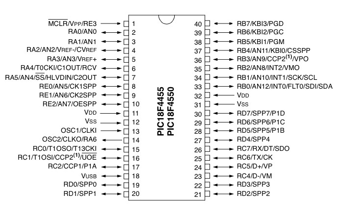
PIC18F4550 can use same basic circuit of PIC16F877A. All pins are similar. PGC, PGD, MCLR, VDD, VDD are use for ICSP programming port.
Important setting in using PIC18F4550
#pragma config PLLDIV = 5 // This value has to be 5 for 20Mhz crystal
#pragma config FOSC = HSPLL_HS // High Speed oscillator for crystal more than 4Mhz
#define _XTAL_FREQ 16000000 // Use 16Mhz although 20Mhz crystal is used
Although 20Mhz crystal is used , _XTAL_FREQ 16000000 has to be define to be 16Mhz because the speed of this PIC is fix at 4Mhz, 16MHz, 48Mhz...If _XTAL_FREQ 20000000, __delay_ms() and __delay_us() function is not accurate. _XTAL_FREQ 16000000 is the only ways I can think to make it accurate.
**If you manage to get accurate delay with _XTAL_FREQ 20000000, please share with me...thanks
18F4550 PIR sensor with LCD display
This project is using PIC18F4550. PIR sensor is used to sense motion. When there is movement, the data pin of PIR sensor will send high signal to PIC. The PIR sensor is very easy to used with PIC as it send digital HIGH and LOW signal only as active HIGH switch. In this project, when there is movement, LCD will shows "object detected" referring to video below.
**PIR sensor needs atleast 5 minutes to be in ready mode. So, delay must be insert before any other program.
Switch controlled LED blinking
Video below shows LED light controlled by forward and reverse switch. When forward button is press, LED will shift to the right and reverse button will make the LED shift to the left. When LED is shifted until the last one, it will back to the first one again.
Programming part
//This is the desired array looks like
unsigned char _options[8]={0b00000001, 0b00000010, 0b00000100, 0b00001000,
0b00010000, 0b00100000, 0b01000000, 0b10000000};
sel=0;
PORTD =_options[sel]; //assign PORTD output to follow the array
//this is where button assigned to move forward or reverse
while(1)
{
if(forward==1)
{
if(sel==7) sel=0;
else sel++;
PORTD =_options[sel];
while(forward==1); //waiting for button to be press
}
else if(reverse==1)
{
if(sel==0) sel=7;
else sel--;
PORTD =_options[sel];
while(reverse==1);
}
Subscribe to:
Posts (Atom)